4 Test Files
All test input files, reference output files, and supporting files can be downloaded as a zip
4.1 Core
| Input | Output | Notes |
|---|---|---|
| ray-sphere.txt |  |
Because there is no sun, nothing is lit. If you see the central sphere but not the one in the corner, the most common reason is failing to normalize ray directions when they are first created. |
| ray-sun.txt | 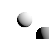 |
Numbers generated for pixel (55, 45)Ray origin: (0, 0, 0)Ray direction: (0.0990148, -0.0990148, -0.990148) Intersection depth: 0.724832 Intersection point: (0.0717691, -0.0717691, -0.717691) Surface normal: (0.23923, -0.23923, 0.94103) Sun direction: (0.57735, 0.57735, 0.57735) Lambert dot product: 0.543304 Linear color: (0.543304, 0.543304, 0.543304) sRGB color: (194, 194, 194) Numbers generated for pixel (82, 70)Ray origin: (0, 0, 0)Ray direction: (0.481108, -0.451039, -0.751731) Intersection depth: 1.20665 Intersection point: (0.58053, -0.544246, -0.907077) Surface normal: (-0.838941, 0.511507, 0.185845) Sun direction: (0.57735, 0.57735, 0.57735) Lambert dot product: -0.0817462 Linear color: (0, 0, 0) sRGB color: (0, 0, 0) |
| ray-color.txt | 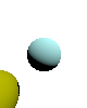 |
This file is useful for debugging but is not awarded points and not generated from your code by the submission server. |
| ray-overlap.txt | 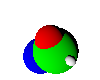 |
|
| ray-behind.txt |  |
There’s another sphere behind the camera that should not be visible. |
| ray-shadow-basic.txt |  |
4.2 Elective
| Input | Output | Notes |
|---|---|---|
| ray-expose1.txt | 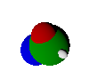 |
low exposure; note the lit colors for some pixels exceed 1 before exposure but are darkened by exposure to a distinguishable range |
| ray-expose2.txt | 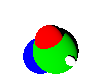 |
high exposure |
| ray-suns.txt | 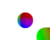 |
several colored suns |
| ray-shadow-suns.txt | 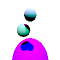 |
multiple suns means multiple shadows |
| ray-view.txt | 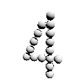 |
moved and rotated camera |
| ray-fisheye.txt |  |
|
| ray-panorama.txt | 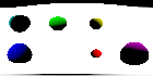 |
|
| ray-plane.txt | 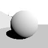 |
two intersecting planes |
| ray-shadow-plane.txt | 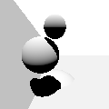 |
multiple planes and spheres intersecting with shadows |
| ray-tri.txt | 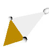 |
tests that triangle boundaries line up with vertex locations |
| ray-shadow-triangle.txt |  |
triangles casting and receiving shadows |
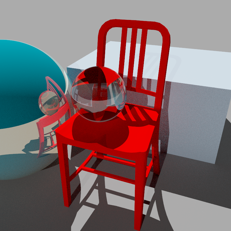
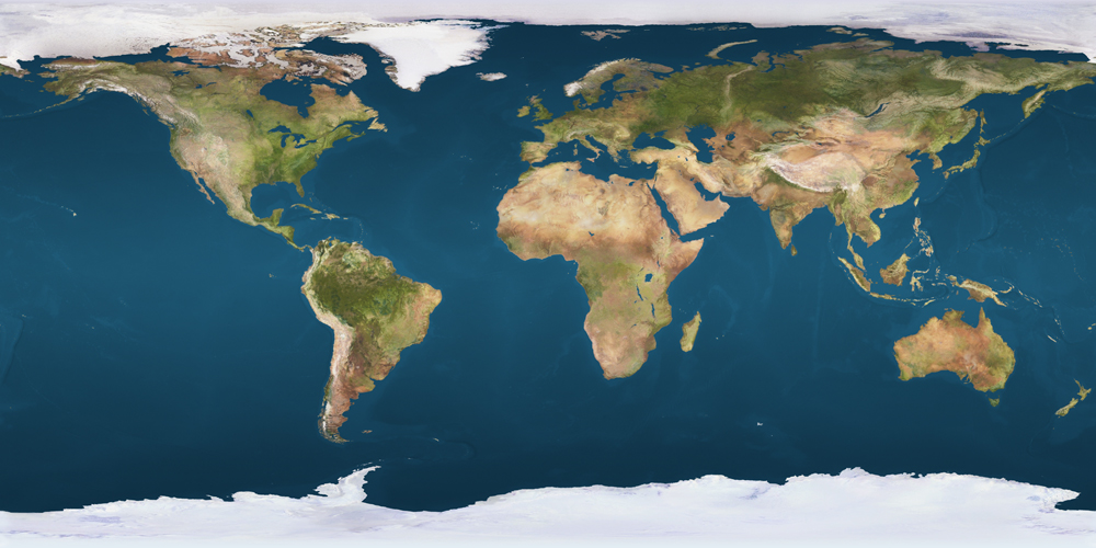
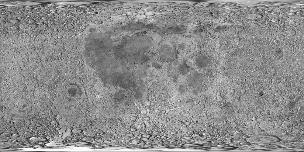
| ray-tex.txt | 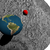 |
spheres with textures; uses earth.png and moon.png as texture maps |
| ray-trit.txt | 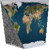 |
triangles with textures; uses earth.png and moon.png as texture maps |
| ray-bulb.txt | 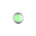 |
two bulbs, one sun; if your image is darker than this one, make sure negative dot products during lighting are clamped to 0 |
| ray-shadow-bulb.txt |  |
spheres with a light between them should not shadow one another |
| ray-neglight.txt | 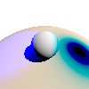 |
one of the lights has negative color, emitting darkness; impossible in the real world but not in a computer |
| ray-shine1.txt | 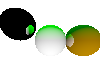 |
colorless reflectivity |
| ray-shine3.txt | 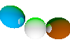 |
colored reflectivity |
| ray-bounces.txt |  |
custom levels of recursion |
| ray-trans1.txt | colorless transparency | |
| ray-trans3.txt | colored transparency | |
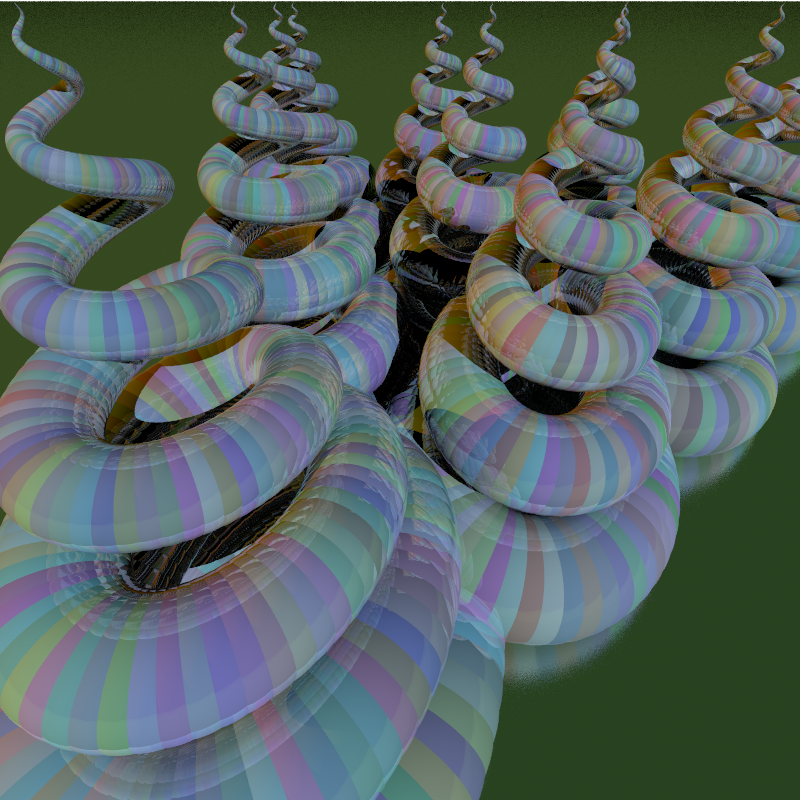
| ray-ior.txt |  |
different indices of refraction on each sphere |
| ray-rough.txt | 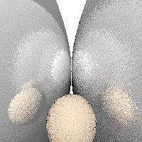 |
different roughness with both reflections and diffuse light; based on random sampling so each run will be slightly different |
| ray-aa.txt |  |
anti-aliasing; based on random sampling so each run will be slightly different |
| ray-dof.txt | 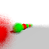 |
depth-of-field effects; based on random sampling so each run will be slightly different |
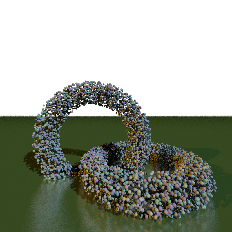
| ray-gi.txt | 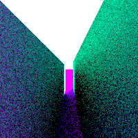 |
global illumination; based on random sampling so each run will be slightly different |
| ray-many.txt | 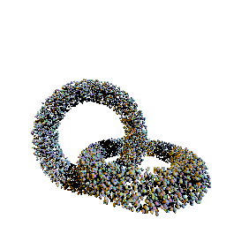 |
10,000 spheres; will be run single-threaded only; a simple BVH adds between a 10× and 50× speedup to this scene |