Many basic terrain modeling algorithms employ something called Perlin noise to create a highly detailed natural appearance. Invented by Ken Perlin in 1982 while working on the movie Tron, Perlin noise uses randomness and repetition to synthesize 2D and 3D textures. In 1997, Perlin won an Academy Award for Technical Achievement from the Academy of Motion Picture Arts and Sciences for this contribution to graphics. Perlin noise and techniques based off of it are still widely used in games and movies today.
Realistic terrain generation in modern games require tools that do more than just model the basic underlying terrain…these tools support operations like creation of vegetation and roads and erosion. See this talk by Ubisoft developer Etienne Carrier if you are interested in seeing the tools technical artists use these days.
Example terrain created with Perlin noise and various additional steps afterward
2 The Faulting Method
The same year (1982) that Ken Perlin crated Perlin Noise, Benoit Mandelbrot proposed a less efficient but easier-to-implement method called the faulting method.
In addition to this page, you can find a summary of the faulting method in section 3.1.2 of the following survey paper on terrain generation algorithms:
A Review of Digital Terrain Modeling. Eric Galin, Eric Guérin, Adrien Peytavie, et al. [PDF]
The overall faulting method process runs as follows:
We will construct a fault plane cutting through the terrain by generating a random point p and random direction vector n to define the plane.
First generate a random point p in the (x,y) bounds of the grid.
Generate a random normal vector n with z=0 for the plane; in other words, (xn,yn,0), where
xn,yn is a point uniformly sampled on the unit circle. If θ is a random angle between 0 and 2π then an appropriate random normal would be
n=(cosθ,sinθ,0).
Then for each vertex b,
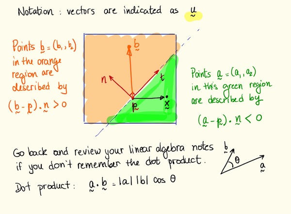
Test which side of the plane that vertex falls on by using the dot product test (b−p)⋅n≥0.
Faulting plane computation using dot products, by Eric Shaffer
If b is in the negative half-space, lower the z coordinate of by some amount Δ. If b is in the positive half-space, raise the z coordinate of by some amount Δ.
Optional You may get better results with distance weighted displacements for Δ, only moving vertices that are relatively close to the faulting plane. To do so compute the distance r=d(b,Φi) from b to the fault plane Φi and alter the Δ you use for each vertex by a coefficient function
g(r)=(1−(r/R)2)2 for r<R and g(r)=0 elsewhere.
R is a parameter you determine.
Once you’re done, you might need to re-scale the vertical axis to get the desired ratio between vertical displacement and horizontal size.